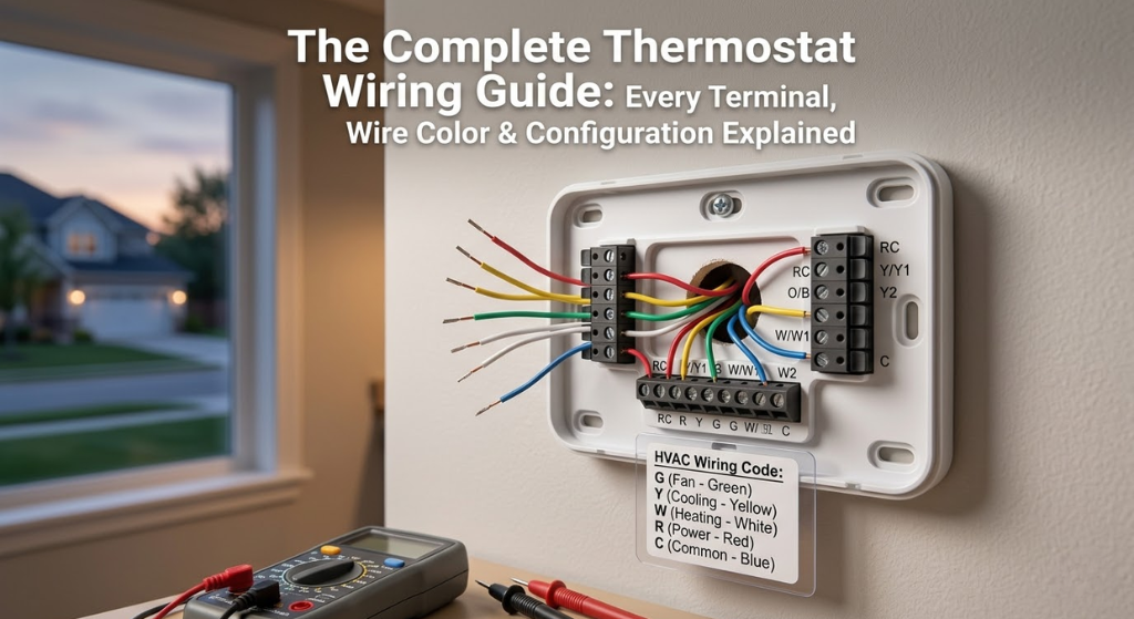
The Complete Thermostat Wiring Guide: Every Terminal, Wire Color & Configuration Explained
From the R wire to O/B heat pump reversing valves — a field-tested, zero-confusion reference for homeowners, DIYers, and HVAC professionals wiring any system.
Why Thermostat Wiring Matters More Than You Think
The thermostat gets credit for controlling your home’s climate, but the real work happens in the thin bundle of low-voltage wires running from it to your furnace, air handler, or heat pump. Get those connections right and your system hums along quietly, hitting setpoints accurately, running at peak efficiency. Get them wrong — even by a single terminal — and you can blow a 5-amp control board fuse, damage a compressor contactor, or leave yourself with no heat on the coldest night of the year.
Residential thermostat wiring runs on 24 volts AC — a transformer on your furnace control board steps down the 120V house current. This low voltage is why most homeowners can safely tackle a thermostat swap themselves. But low-voltage does not mean consequence-free: shorting wires together while the system is powered can blow the transformer entirely, turning a $30 thermostat swap into a $150 service call.
This guide covers every aspect of thermostat wiring — from the colour of the wire in your hand to the letter on the terminal board to what happens electrically when you turn the dial. Whether you are replacing a mechanical dial with a smart model, upgrading from a 2-wire heat-only system to 5-wire cooling, or diagnosing why your furnace will not fire, you will find the answer here.
Safety First: Non-Negotiable Steps Before Touching a Wire
Thermostat wiring is genuinely accessible for confident DIYers. The voltage is low, the connections are screw terminals or push-in clamps, and most swaps take under an hour. But three specific hazards catch people out:
- Accidentally shorting wires mid-change: A bare wire brushing against another while the system is powered can blow the transformer. Always kill power first.
- Misidentifying line voltage as low voltage: Some older electric baseboard and radiant systems run 120V or 240V to the thermostat location — not 24V. If you see heavy-gauge, insulated wires rather than the thin 18-gauge bundle you expect, stop and verify voltage with a meter. Consult our guide on line voltage vs. low voltage thermostats before proceeding.
- Wires falling back into the wall: If a wire drops past the drywall opening before you have labelled it, retrieving it is a significant headache. Tape labelled wires to the wall or use the wire labels supplied with your new thermostat.
One habit separates successful thermostat swaps from problematic ones: photograph the existing wiring before removing a single wire. A clear picture of each wire and its terminal from two or three angles costs you ten seconds and potentially saves hours of troubleshooting. Include the terminal labels in the frame.
Tools You Need for the Job
A thermostat swap does not require an HVAC technician’s toolbox. Here is the complete practical kit:
| Tool | Why You Need It | Notes |
|---|---|---|
| Non-contact voltage tester | Confirm power is off before touching wires | ~$15 — do not skip this |
| Small Phillips screwdriver (#2 and #1) | Remove thermostat faceplate; tighten terminal screws | Magnetic tip helpful |
| Flathead screwdriver (small) | Loosen push-in wire clamps; pry gaskets | 2.5mm blade width ideal |
| Wire stripper | Strip insulation if adding new wires or splicing | Set for 18 AWG |
| Needle-nose pliers | Grip small wires, retrieve dropped wires from wall | Curved nose preferred |
| Smartphone / camera | Photograph existing wiring before disconnect | The single most important tool |
| Masking tape + marker | Label each wire with its terminal letter | Also included with most smart thermostats |
| Multimeter (optional but useful) | Verify 24V between R and C; check continuity | Essential if troubleshooting |
| Electrical tape | Insulate any exposed wire ends not in use | Don’t leave bare copper loose |
| Torpedo level | Mount base perfectly straight | A crooked thermostat will bother you forever |

Klein Tools Non-Contact Voltage Tester — the #1 Safety Tool
Confirm the power is truly off before touching any thermostat wiring. Fast, reliable, and under $20.
🛒 Check Price on AmazonEvery Thermostat Terminal Label Decoded
The lettered terminals on a thermostat’s backplate are the heart of the system. Each letter represents a specific circuit function, and connecting the wrong wire to the wrong terminal — even if it powers on initially — can cause incorrect system behaviour or equipment damage over time. Below is the complete reference.
Thermostat Wire Colour Codes: The Complete Reference Table
Standard 18-gauge thermostat cable comes in bundles of 2 to 10 wires, each in a defined colour. The table below shows the conventions — memorise it and you will rarely be confused when you open up a wall.
| Wire Colour | Standard Terminal | Function | Alt. Terminal |
|---|---|---|---|
| Red | R, RC, or RH | 24V power from transformer | — |
| White | W or W1 | Stage 1 heat | W2 on multi-stage |
| Green | G | Fan / blower | Sometimes C in a pinch |
| Yellow | Y or Y1 | Stage 1 cooling / compressor | Y2 on two-stage |
| Blue | C | Common wire — completes 24V circuit | Sometimes X or B on Trane |
| Orange | O | Heat pump reversing valve (energised cooling) | — |
| Brown | W2 / AUX | Second-stage heat or auxiliary heat strip | — |
| Black | C or Y2 | Common wire (if blue not present); or Stage 2 cooling | Varies — always verify |
The C-Wire Problem: Why It Matters and All Your Options
The C wire — “common” — is the return path that completes the 24V circuit between the transformer and the thermostat. Older thermostats ran on batteries or drew tiny parasitic power from the control wires and did not need it. Every modern Wi-Fi smart thermostat does.
Without a C wire, a smart thermostat either runs off its own batteries (which drain quickly when Wi-Fi is always on), or uses “power stealing” — drawing micro-current from other wires when they are not actively signalling. Power stealing works on many systems but fails on others, causing the furnace to cycle on and off unexpectedly, the thermostat to display low-battery warnings, or the Wi-Fi to drop repeatedly. If your smart thermostat keeps rebooting or losing Wi-Fi, a missing or poorly connected C wire is almost always the first thing to check.
Option 1: Use an Existing Spare Wire
Most thermostat cables have 5 or 8 wires. If your system only used 4 (R, W, Y, G), there is almost certainly a 5th wire sitting idle in the bundle. Go to the furnace end, locate the control board’s C terminal, connect the spare wire there, then connect the other end to C at the thermostat. This is free, takes 20 minutes, and is the cleanest solution.
Option 2: C-Wire Adapter (Add-a-Wire)
Products like the Venstar Add-a-Wire or the Nest Power Connector use signal multiplexing to carry power to the thermostat through only four wires — effectively creating a virtual fifth wire. Installation involves connecting a small module at the furnace control board. These work reliably on most systems for around $20.
Option 3: Replace the Thermostat Cable
If the existing cable has fewer than 5 conductors or is damaged, running a new 18/8 (18-gauge, 8-conductor) cable is the permanent, future-proof solution. This is the right choice if you are also upgrading to a two-stage system, adding a heat pump, or if you want the flexibility for future smart home additions. See our detailed guide on extending or splicing thermostat wiring for a step-by-step approach.
Option 4: Use a Smart Thermostat with Its Own Adapter
Several smart thermostats — the Ecobee with its PEK (Power Extender Kit), and some Honeywell models — include an adapter in the box specifically to work around a missing C wire. If you already have the thermostat, check the box before running new wire.
| Solution | Cost | Skill Level | Reliability | Best For |
|---|---|---|---|---|
| Spare wire repurpose | Free | Beginner | ⭐⭐⭐⭐⭐ | Cable with unused wire |
| Add-a-Wire adapter | ~$15–25 | Beginner | ⭐⭐⭐⭐ | No spare wire, single-stage system |
| PEK / built-in adapter | Included | Beginner | ⭐⭐⭐⭐ | Ecobee, select Honeywell |
| New 18/8 cable | $40–$100 + time | Intermediate | ⭐⭐⭐⭐⭐ | Future-proof installs, heat pump upgrades |
| Power stealing only | Free | None needed | ⭐⭐ (system dependent) | Last resort only |

Venstar Add-a-Wire — Install Any Smart Thermostat Without a C-Wire
Works with most single-stage and two-stage systems. Simple 10-minute install at the furnace control board. No new wiring required.
🛒 Check Price on AmazonConventional Heating & Cooling Wiring Configurations
A “conventional” system means a gas, oil, or electric furnace paired with a standard split-system central air conditioner. These are the most common residential setups in North America and the most straightforward to wire.
2-Wire Heat-Only System (Heating Only, No AC, No Fan Control)
The simplest possible configuration — often found in apartments or older homes with boiler heat:
- Red → R
- White → W
No fan terminal, no cooling. The furnace or boiler turns on when the thermostat closes the R-to-W circuit. Many modern smart thermostats will not work on 2-wire systems without a C-wire adapter.
4-Wire Heat + AC (No Separate Fan Control)
- Red → R
- White → W
- Yellow → Y
- Green → G
5-Wire Heat + AC + Common (The Modern Standard)
- Red → R
- White → W
- Yellow → Y
- Green → G
- Blue → C
Understanding the Blower Motor Relationship
The G terminal does more than you might think. When the thermostat calls for cooling (Y energises), it also energises G automatically through the control board — the blower runs any time the compressor runs. When G is energised independently (fan-only mode on the thermostat), only the blower runs, no conditioning. This air circulation matters more than most homeowners realise. Understanding blower motor types — and whether your system uses a standard PSC or the more efficient ECM variable-speed motor — directly affects how much electricity the “fan always on” circulation mode consumes each month.
Heat Pump Wiring: The O/B Terminal and Why It Gets Confused
Heat pump systems are mechanically similar to air conditioners but can run in reverse — extracting heat from cold outdoor air and moving it indoors in winter. This reversal is controlled by a component called the reversing valve, which is wired through the O or B terminal on the thermostat. Getting this terminal wrong is one of the most common heat pump wiring mistakes and produces a very specific symptom: the system heats when you call for cooling and cools when you call for heating.
Standard Heat Pump Wiring (5 or 6 wires minimum)
- Red → R — power
- Blue → C — common
- Yellow → Y — compressor
- Green → G — fan
- Orange → O — reversing valve (most brands)
- White → W/AUX — auxiliary/backup heat strips
O vs B: The Brand-Specific Distinction
Nearly every heat pump manufacturer (Carrier, Trane, Lennox, Goodman, Mitsubishi) uses the O terminal convention — the reversing valve is energised during cooling. Rheem and Ruud use the B convention — the reversing valve is energised during heating. When you install a thermostat, you configure it for O or B in the settings menu. Choosing incorrectly will make your heat pump blow cold air when you want heat and vice versa. The fix is as simple as changing the setting — no rewiring required.
Heat Pump + AUX Heat Wiring
Most ducted heat pump systems include electric resistance backup strips for extremely cold days when the heat pump cannot meet demand alone. These connect via W2 or AUX terminal. The thermostat activates them automatically when the outdoor temperature drops below the heat pump’s effective operating range (typically around 35°F / 2°C) or when the system has been calling for heat for too long without reaching setpoint. For a detailed look at multi-zone heat pump thermostat compatibility, see our Nest vs Honeywell multi-stage HVAC comparison.
Two-Stage and Multi-Stage System Wiring
Two-stage and variable-capacity HVAC systems are increasingly common because they deliver meaningfully better comfort and efficiency than single-stage equipment. The first stage runs the system at reduced capacity (typically 65–70% of full output) for most of the time — quieter, more even temperatures, better dehumidification. The second stage kicks in only when demand exceeds what stage one can handle.
Two-Stage Furnace Wiring
Add a W2 connection to the standard 5-wire configuration:
- Red → R
- White → W1 (stage 1 heat)
- Brown → W2 (stage 2 heat)
- Yellow → Y1
- Green → G
- Blue → C
Communicating Systems: A Different Animal
Some premium HVAC brands — Carrier Infinity, Trane ComfortLink, Lennox iComfort — use proprietary digital communication protocols rather than standard 24V switching. These systems use only 4 wires labelled A, B, C, D (or similar) and require a matching proprietary thermostat. If you open your thermostat and see non-standard terminal labels or a flat ribbon cable rather than individual coloured wires, you have a communicating system. Do not attempt to wire a standard smart thermostat to it without confirmed compatibility.
Boiler and Radiant Heating System Wiring
Boilers and radiant heating systems — whether hydronic baseboard, in-floor radiant, or steam radiators — use the thermostat wiring purely for zone valve or boiler relay control. There is no cooling circuit, no Y wire, no G wire. These systems are electrically simpler than forced-air setups but have their own quirks.
Single-Zone Boiler: The Simplest Setup
Most standalone single-zone boiler thermostats need only two wires:
- Red → R
- White → W
When the thermostat calls for heat, it closes the R-to-W circuit, which energises the zone valve or boiler relay. The boiler fires, circulator pumps run, and hot water circulates through the system. The thermostat needs no C wire if it runs on batteries — but smart thermostats will need one.
Multi-Zone Boiler Systems
Multi-zone hydronic systems use a zone controller board (like the Honeywell HZ311) that manages multiple zone valves and the boiler itself. Each thermostat wires independently to its zone’s terminals on the controller. Replacing these thermostats while retaining the zone controller requires matching the existing wiring scheme — matching the existing wiring scheme carefully is essential — the zone controller board handles priority logic and pump sequencing, so thermostat wiring feeds into a more complex control system than a standard single-zone setup.
Temperature Differential for Boiler Systems
Unlike forced-air systems where a 0.5°F differential is fine, boilers benefit from a wider switching differential — typically 1–2°F — to prevent short-cycling, which stresses the heat exchanger over time. If your smart thermostat allows you to configure the differential (sometimes called “swing”), set it appropriately for your heating system type.

18/8 Thermostat Wire — Run a New Cable the Right Way
8-conductor 18 AWG CL2 rated. Enough wires for heat pump + two-stage + humidifier. Future-proof your installation.
🛒 Check Price on AmazonSmart Thermostat Wiring: What Changes (and What Doesn’t)
The wiring terminals on a smart thermostat are identical to those on a conventional programmable model — R, C, W, Y, G, O/B. The physical connections you make are exactly the same. What changes is the requirement for continuous power and the expanded capabilities that come from the thermostat running software rather than simple switching logic.
Why the C Wire Is Non-Negotiable for Smart Thermostats
A conventional programmable thermostat draws a few milliamps from the HVAC system’s power wires when it calls for heating or cooling. Its microcontroller and display are simple enough to run on batteries. A smart thermostat runs Wi-Fi, a colour touchscreen or LED display, occupancy sensors, and potentially radar chips — drawing 100–200mA continuously. Batteries would last days at best. The C wire providing a constant 24V return path is how the thermostat powers itself without depleting batteries or stealing current from control wires.
Smart Thermostat Terminal Compatibility Checks
Before purchasing a smart thermostat, use the manufacturer’s compatibility checker (Nest, Ecobee, and Honeywell all have online tools) with your existing wire labels. Key incompatibilities to watch for:
- Systems with K, U, or proprietary communication terminals (communicating systems)
- Line voltage systems (120V/240V) — standard smart thermostats are 24V only
- Systems with G1, G2, G3 (multi-speed fan control) — not standard smart thermostat territory
- Millivolt systems (some gas fireplaces and old gravity furnaces) — require millivolt-specific thermostats
Step-by-Step Thermostat Installation
This is the universal procedure — adaptable to any system type covered in this guide. Steps 1–4 are non-negotiable regardless of system complexity.
- Kill power at the breaker. Turn off the furnace/air handler circuit and, for systems with cooling, the outdoor condenser circuit. Verify the thermostat display is dark and confirm with your non-contact voltage tester at the thermostat terminals.
- Photograph the existing wiring from multiple angles. Include the terminal labels in the frame. Take 3–4 shots so you have redundancy. This is your insurance policy.
- Remove the thermostat faceplate. Most pull straight off; others lift from the bottom. Locate the backplate screws and remove them.
- Label every wire before disconnecting anything. Use the adhesive labels supplied with the new thermostat, or masking tape with a permanent marker. Write the terminal letter on each wire’s label. Do not trust your memory — label as you go, one wire at a time.
- Disconnect wires from the old terminal block. Loosen screw terminals or depress push-in release buttons. Catch each wire immediately — tape them to the wall if needed to prevent them dropping back inside.
- Remove the old backplate. Unscrew from the wall. Check whether the new backplate covers the old mounting holes — if not, patch and paint before proceeding.
- Mount the new backplate. Feed wires through the central opening. Use a torpedo level to confirm the plate is straight before marking and drilling screw holes. Drive anchors into drywall — smart thermostats are heavier than mechanical dials.
- Connect wires to the new terminal block. Match each labelled wire to its corresponding terminal — refer to your photographs and the tables in this guide. Strip 1/4 inch of insulation if needed. For screw terminals, wrap wire clockwise around the screw. For push-in connectors, insert firmly until you feel a positive click.
- Check the RC/RH jumper situation. Single transformer systems need RC and RH connected together. Verify the new thermostat’s jumper is installed if you only have one R wire.
- Tuck wires carefully and attach the thermostat faceplate to the backplate. Do not pinch any wires. The faceplate should click or screw firmly — it should not flex when pressed.
- Restore power at the breaker and complete the thermostat setup wizard. Configure system type (conventional/heat pump), fuel type, staging, and C-wire settings per the manufacturer’s instructions.
- Test every function systematically. Call for heat — verify the furnace fires within 3–5 minutes and the fan runs. Call for cooling — verify the compressor starts and cold air is delivered. Test fan-only mode. On heat pumps, test both heat and cool modes and verify the reversing valve behaviour is correct.
Wiring Troubleshooting: Diagnosing the 10 Most Common Problems
| Symptom | Most Likely Wiring Cause | Fix |
|---|---|---|
| Thermostat completely dead after install | Blown control board fuse (wires shorted) | Replace 3–5A fuse on control board |
| No heat, thermostat shows “Heat On” | W wire not reaching furnace board, or poor W connection | Check W at both ends; verify control board W terminal secure |
| Fan runs constantly, no heating/cooling | G wire shorted to R or shorting internally | Inspect G terminal and wire for nick; check insulation |
| Heat pump heats when calling cool | O/B configured wrong (O selected but should be B, or vice versa) | Change O/B setting in thermostat system menu |
| AC runs briefly then shuts off, repeats | C wire absent or poor; transformer brownout | Add C wire or verify C connection is solid at both ends |
| Smart thermostat shows “low battery” immediately | No C wire; power stealing failing on this system | Install C wire or Add-a-Wire adapter |
| Two-stage system only uses one stage | W2 or Y2 not wired or thermostat not configured for 2-stage | Check W2/Y2 terminal; configure in thermostat system settings |
| Thermostat works but display keeps rebooting | Voltage drop on C wire — long cable run, poor splice | Check C wire continuity; re-splice if daisy-chained; measure 24V AC at terminal |
| System won’t come on at all | R wire not connected or broken in the wall | Verify 24V AC between R and C with multimeter; trace R wire to transformer output |
| AUX heat on but compressor not running | E or W2 wired incorrectly into the emergency heat circuit | Verify E terminal configuration; confirm system type set to heat pump, not conventional |
For a comprehensive diagnostic walk-through that goes beyond wiring to cover control board faults, transformer failures, and low-voltage signal issues, working through the possible faults systematically — transformer, fuse, wiring, and control board — is the most efficient diagnostic path.
Voltage Testing: Using a Multimeter to Confirm Connections
When you cannot determine the cause of a wiring problem by visual inspection alone, a multimeter set to AC voltage (20V range) provides definitive answers. Here is the testing sequence every homeowner should know:
- Test for 24V AC between R and C. With the system powered on and the thermostat NOT connected, probe R and C at the thermostat terminal block. You should read 24–28V AC. No reading means the transformer is not producing power, or the R/C wires are broken or disconnected at the furnace end.
- Test each control wire to C while calling for that function. Set the thermostat to call for heat — then measure from W to C at the furnace terminal block. You should see 24V AC when the thermostat is actively calling. No voltage means the thermostat is not sending the call signal, or the wire is broken between the two ends.
- Test the 5-amp control fuse. Pull the mini blade fuse from its holder on the control board. Set your multimeter to continuity (beep mode). Touch probes to both ends of the fuse. A blown fuse will not beep. A good fuse beeps immediately. Replace blown fuses only with identical amp-rated fuses — a 5A fuse in a 3A rated slot creates a fire risk at the control board.
- Check for voltage at the transformer secondary. The furnace transformer has two sets of terminals — primary (120V from house supply, do NOT touch) and secondary (the 24V low-voltage output). Measuring 24V AC at the secondary terminals confirms the transformer is functioning. Readings significantly below 20V under load indicate a failing or undersized transformer that needs replacement.
Understanding the Furnace Control Board in the Circuit
The furnace control board is the hub that receives signals from the thermostat and acts on them by energising gas valves, blower motors, ignitors, and outdoor condenser contactors. When wiring troubleshooting points to a problem not in the thermostat cable itself, the control board is the next item to investigate. Board faults that mimic wiring problems include: a cracked board causing intermittent contact under thermal cycling, a failed output relay that prevents a control signal from reaching its destination, or a stuck relay that keeps a circuit energised even when the thermostat has stopped calling for it.
Visual inspection of the control board with power off can reveal burnt traces, cracked solder joints, or a bulging capacitor — all signs of board-level failure that wiring changes alone will not resolve. If the board looks physically damaged, replacement is the correct path. Boards for common brands (Carrier, Trane, Lennox, Goodman) are typically available for $60–$180 online and are within the skill range of a confident DIYer who understands the wiring principles covered in this guide.
Wire Gauge and Cable Specifications
Standard residential thermostat cable is 18 AWG (American Wire Gauge) solid copper, designated as 18/5 (5 conductors), 18/8 (8 conductors), and so on. The gauge is important: thinner wire (higher AWG number) has higher resistance, which can cause voltage drop over long runs — contributing to the C-wire instability issues described earlier. Never substitute 22 AWG thermostat wire for 18 AWG on runs over 50 feet. For very long runs (over 100 feet from furnace to thermostat, common in large multi-story homes), 18/8 remains appropriate but verify you are measuring 24V AC at the thermostat end, not just at the transformer.
The insulation rating matters too: thermostat cable should be rated CL2 or higher for in-wall installation. This is a National Electrical Code requirement — CL2 rated insulation can withstand the temperatures found inside wall cavities, which can be significantly higher than room air temperature in summer. Most thermostat cable sold at home improvement stores is CL2 compliant, but verify if you are buying from an industrial supplier.
When to Call a Professional
Most thermostat wiring tasks are firmly within homeowner DIY territory. These specific situations warrant professional HVAC involvement:
- Line voltage systems (120V/240V): If your thermostat location has heavy-gauge wires — visibly thicker than the thin 18 AWG bundle you expect — confirm voltage before touching anything. Line voltage work requires a licensed electrician, not HVAC DIY skills.
- Communicating HVAC systems: Proprietary protocols (Carrier Infinity, Trane ComfortLink, Lennox iComfort) require manufacturer-specific thermostats and setup tools beyond standard wiring.
- New refrigerant line sets or outdoor equipment: Thermostat wiring changes that also involve refrigerant circuit modifications require EPA 608 certification. Wiring the thermostat is DIY; touching refrigerant is not.
- Persistent shorts or burning smells: If a replacement fuse blows immediately on restore, or if you smell burning at the control board, power off the system entirely and call for service. There is a fault more serious than a wiring mistake.
- Complex multi-zone hydronic systems: Systems with multiple pumps, outdoor reset controls, and more than three zones involve zone controller programming beyond standard thermostat wiring scope.
✅ Signs Your Wiring Is Correct
- Thermostat powers on immediately after restore
- Each function test (heat/cool/fan) activates the correct equipment
- Smart thermostat connects to Wi-Fi without connectivity issues
- No intermittent reboots or “low battery” warnings
- Heat pump blows warm in heat mode and cool in cool mode
❌ Signs Something Is Wrong
- Blank display after power restore (fuse or dead wire)
- Calling for heat runs the AC compressor instead
- Fan runs continuously when system should be idle
- System short-cycles (starts and stops every few minutes)
- Thermostat reboots or drops Wi-Fi repeatedly
Advanced Wiring Tips: What the Installation Manual Doesn’t Tell You
After covering the fundamentals, a handful of practical insights separate a technically correct installation from one that works flawlessly for years. These are the details that experienced HVAC technicians know from repetition, but that first-time installers often only discover after a callback.
Pre-Strip Wire Ends at the Furnace, Not Just the Thermostat
Most people strip wire ends at the thermostat when installing a new model. Fewer people check the wire connections at the furnace control board. Over years of thermal cycling, vibration, and occasional moisture, the wire ends at the furnace board can develop micro-corrosion — a thin layer of oxidation on the copper that increases resistance and can cause intermittent signal loss. While you have the system opened up for a thermostat swap, go to the furnace, loosen the terminal screws one at a time, pull each wire back about half an inch, trim the oxidised copper tip, strip a fresh 1/4 inch, and reseat the wire. This takes an extra 10 minutes and eliminates one of the leading causes of mysterious intermittent HVAC problems that appear weeks or months after installation.
Foam Sealant in the Wall Opening
The hole in your wall where thermostat wires pass through is a direct conduit for cold drafts, conditioned air leaks, and — importantly — for cold air from the wall cavity to reach the thermostat sensor. If the thermostat is mounted on an exterior wall or a wall bordering an unheated space, the air coming through that opening can be significantly colder than room air, causing the thermostat to read a lower temperature than the room actually is and over-heat the space. After connecting all wires, stuff the opening around the cable with a small amount of fire-rated foam sealant or a piece of non-flammable insulation material before mounting the backplate. This improves temperature accuracy and eliminates a surprisingly common source of comfort complaints in new smart thermostat installations.
The Thermostat Location Problem Most People Ignore
The best wiring job in the world cannot compensate for a thermostat mounted in a poor location. The most common location problems are: placement in a hallway that receives little actual occupancy (the thermostat serves a space that is colder or warmer than the living areas it is meant to control); proximity to a supply air register (the thermostat senses conditioned air directly from the duct, rather than the room’s ambient temperature); placement on an exterior wall where wall cavity temperatures influence the reading; and direct sunlight exposure for part of the day. If you are running new wiring anyway, consider whether the existing thermostat location is actually representative of where people spend time in the home. Moving the thermostat to a better location often delivers more comfort improvement than upgrading the thermostat model.
Documenting Your Wiring Configuration
After completing any thermostat installation, take a moment to create a permanent record. Photograph the thermostat backplate with all wires connected and the terminal labels visible. Photograph the furnace control board with the thermostat wiring connected. Write down the system type (conventional/heat pump), staging (single/two-stage), fuel (gas/oil/electric), and the wiring configuration you ended up with. Store this documentation in one of three places: taped inside the furnace cabinet, in a home maintenance folder, or in a cloud folder you will be able to find in 10 years. When the next technician, next owner, or future-you needs to understand the system, this 5-minute documentation effort saves hours of investigation.
Smart Thermostat Energy Optimisation After Correct Wiring
Getting the wiring right is the foundation — but the full value of a smart thermostat comes from configuring it correctly after installation. The core features that deliver real energy savings are geofencing (the thermostat shifts to an energy-saving setback when your phone leaves the home’s GPS radius), scheduling (consistent setbacks during sleep and away hours can reduce heating and cooling bills by 10–15%), and learning mode on capable models. These features only work reliably when the C wire is properly connected — providing the continuous power the thermostat needs to maintain its Wi-Fi connection and respond dynamically to occupancy signals.
Thermostat Wire as a Diagnostic Tool
Experienced technicians know that you can test HVAC component function directly using the thermostat wiring, without needing to access the equipment itself. By momentarily using a jumper wire to bridge R to W at the thermostat terminal block (with the thermostat disconnected), you send a direct 24V call for heat to the furnace, bypassing the thermostat entirely. If the furnace fires with a direct wire jump but not through the thermostat, the fault is in the thermostat. If it does not fire with a direct jump, the fault is downstream — in the furnace control board, gas valve, or ignition system. This simple diagnostic technique divides the problem space in half instantly and is one of the most useful things a homeowner can know about how their HVAC control circuit works.
Thermostat Wiring: Frequently Asked Questions
What do the letters on thermostat terminals actually mean?
Each letter represents a specific circuit function. R (or RC/RH) is the 24V power supply from the furnace transformer. C is the common wire that completes the power circuit. W controls first-stage heating. Y controls first-stage cooling. G controls the fan/blower. O or B controls the reversing valve on heat pumps. W2/AUX controls second-stage heat or backup electric strips. E activates emergency heat mode on heat pump systems.
Do I need a C wire for a smart thermostat?
Almost always yes. Smart thermostats require continuous power for Wi-Fi, displays, and sensors — which batteries cannot sustain reliably and “power stealing” from control wires does not provide consistently. If you do not have a C wire, your options are: repurposing an unused wire in the existing cable, installing an Add-a-Wire adapter at the furnace, running a new 18/8 cable, or using a thermostat that includes its own adapter (like Ecobee with PEK).
What is the difference between RC and RH terminals?
RC is the 24V power supply from the cooling transformer. RH is the 24V power supply from the heating transformer. In the vast majority of residential homes, a single transformer powers both heating and cooling, meaning you have one R wire. That wire connects to R, and a jumper bridges RC to RH internally. Only homes with truly separate heating and cooling transformers — typically those with a boiler for heat and a central AC unit with its own transformer — need separate RC and RH connections.
Why does my heat pump blow cold air in heat mode after I installed a new thermostat?
This is almost always caused by the O/B reversing valve terminal being configured for the wrong mode. Most heat pumps use the O convention — the reversing valve is energised during cooling. But Rheem and Ruud systems use B — energised during heating. Go into your thermostat’s system settings and switch between O and B configurations. No rewiring is required; this is a software setting. Test immediately after changing the setting by calling for heat and verifying warm air delivery.
Can I use the G (green/fan) wire as a C wire?
Technically yes, in some configurations — but you will lose independent fan control if you do. When G is repurposed as C, you can no longer run the fan without an active heating or cooling call. Some people find this acceptable; others miss the “fan only” circulation mode for air filtration. It is better practice to use a genuinely spare wire (one not connected at either end) or install an Add-a-Wire adapter to preserve all functions.
What causes the control board fuse to blow when I replace a thermostat?
The most common cause is two bare wire ends briefly touching each other or a terminal while the power is on. Even a fraction of a second of contact between R and any other wire — especially W, Y, or G — causes a short that blows the 3–5 amp mini fuse on the furnace control board. Always kill power at the breaker before disconnecting or connecting any wires. If it has already happened, locate the mini-blade fuse on the control board (usually clipped into a holder near the 24V transformer), test it with a multimeter, and replace it with an identical amp-rated fuse.
How many wires does a thermostat need?
It depends on your system type. A heat-only system (boiler or furnace without AC) needs just 2 wires (R and W), though 3 are needed if a C wire is required. A standard heating and cooling system with fan control needs 4–5 wires (R, W, Y, G, and ideally C). A heat pump system needs 5–6 wires minimum (R, C, Y, G, O/B, and W/AUX for backup heat). A two-stage system with humidifier control can require 8 wires. When running new wire, always use 18/8 — the extra conductors cost almost nothing and future-proof the installation.
Is thermostat wiring safe for a DIYer to do?
Yes, for standard 24V low-voltage systems. The voltage is safe enough that it cannot electrocute you, and the connections are simple screw or push-in terminals. The main risks are blowing a control board fuse (easily fixable with a $2 replacement) or connecting wires incorrectly (usually resulting in the system not operating rather than damage). The clear exceptions: line voltage systems (120V/240V electric baseboard or radiant), communicating HVAC systems, and heat pump installations where you are also adding refrigerant lines or modifying outdoor equipment. Those warrant professional involvement.
What does W2 or AUX on a thermostat do?
W2 controls second-stage heating on a two-stage furnace — when the thermostat has been calling for heat for an extended period and stage 1 cannot satisfy demand, it activates W2 to engage the furnace at higher capacity. On a heat pump system, the same terminal (often labelled AUX or E) controls the electric resistance backup strips — the emergency heat that kicks in when outdoor temperatures are too low for efficient heat pump operation. The thermostat activates AUX automatically based on outdoor temperature or demand deficit; the user can also activate emergency heat manually through the thermostat menu.
My thermostat wires have no colours — how do I identify them?
Go to the furnace end of the cable. Locate the control board and identify which wire connects to which labelled terminal there — R, W, Y, G, C, etc. The terminal label at the furnace is definitive. Label each wire at the thermostat end with its furnace terminal letter before disconnecting anything at the thermostat. If you cannot access the furnace end or the wires are completely unmarked, use a multimeter in continuity mode: connect one probe to a terminal at the furnace, then touch the other probe to each wire at the thermostat until you find the matching wire.
Your Thermostat Wiring Reference, Any Time You Need It
Bookmark this guide and return to it any time you tackle a thermostat swap or HVAC upgrade. Whether you are wiring a basic 2-wire boiler thermostat, installing a smart model on a multi-stage heat pump, or hunting down a wiring fault that is causing short-cycling — the terminal reference, colour code tables, and troubleshooting matrix have you covered.
🛒 Shop Smart Thermostats on Amazon