- 01. The Core Difference
- 02. How Each Mode Works
- 03. Wiring & Terminals
- 04. Control Logic Differences
- 05. Single vs. Multi-Stage
- 06. Heat Pumps: The Special Case
- 07. Dual-Fuel Systems
- 08. Thermostat Types by System
- 09. Smart Thermostat Differences
- 10. How to Choose the Right One
- 11. Common Mistakes to Avoid
- 12. Seasonal Operation Tips
- FAQs
- Conclusion
Thermostat
Thermostat
Ask most homeowners whether their thermostat controls heating or cooling and you’ll get a shrug. “Both, I guess?” And for most modern homes, that’s correct — but it glosses over a surprisingly important set of technical differences that affect wiring, control logic, staging behavior, and compatibility with specific HVAC equipment.
The reality is that heating and cooling control are fundamentally different electrical and mechanical processes. A furnace needs a simple call-to-fire signal. An air conditioner needs to start a compressor and manage refrigerant flow. A heat pump needs to do both — and reverse direction between seasons. Each demands different wiring terminals, different control logic, and different thermostat capabilities to operate correctly.
This guide breaks down every meaningful difference between heating and cooling thermostats — from the basic wire terminals to multi-stage staging, heat pump reversing valves, and how modern smart thermostats navigate all of it. Whether you’re buying your first smart thermostat, troubleshooting a system that won’t heat or cool correctly, or simply trying to understand what all those colored wires actually do, this is the reference you need.
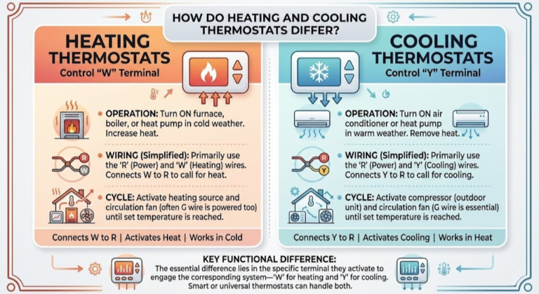
The Core Difference: What a Thermostat Actually Controls
At its most fundamental level, a thermostat is a switch — a device that monitors room temperature and closes or opens an electrical circuit to tell your HVAC equipment when to run. The difference between heating and cooling control comes down to which circuit gets switched, and how the logic for switching it works.
🔥 Heating Mode
- Thermostat calls for heat when room temp drops below the setpoint
- Sends a 24V signal on the W wire to the furnace control board
- Furnace ignites; blower fan starts after a heat exchanger warm-up delay
- System shuts off when room temp rises to the setpoint
- Deadband (typically 1–2°F) prevents rapid cycling around the setpoint
❄️ Cooling Mode
- Thermostat calls for cooling when room temp rises above the setpoint
- Sends a 24V signal on the Y wire to the compressor contactor
- Compressor starts; blower fan runs simultaneously (G wire)
- System shuts off when room temp drops to the setpoint
- Minimum compressor run time (usually 3–5 min) prevents rapid short-cycling
The crucial insight here is that these are opposing control directions. Heating responds to a temperature that is too low; cooling responds to one that is too high. Both use the same 24V low-voltage control system, but they activate entirely different equipment — and require different terminals, different wiring, and often different internal relay configurations in the thermostat itself.
A thermostat designed exclusively for heating doesn’t have a Y terminal at all. A cooling-only thermostat lacks a W terminal. Most thermostats sold today are combined units that handle both — but understanding the underlying separation explains why compatibility issues arise, why heat pump wiring looks so different, and why certain thermostat models don’t work with certain systems.
How Heating and Cooling Systems Work Under Thermostat Control
To appreciate why heating and cooling thermostats differ, it helps to trace exactly what happens from the moment the thermostat sends a signal to the moment your home reaches the set temperature. The sequence is very different for furnaces versus air conditioners, and it directly influences what the thermostat needs to do.
The Furnace Control Sequence
When a heating thermostat sends a call for heat (closing the R-to-W circuit), the furnace control board receives 24V at the W terminal. From there, a tightly choreographed sequence unfolds:
- The draft inducer motor starts, pulling air through the combustion chamber and confirming proper airflow via a pressure switch
- The hot surface igniter or spark igniter energizes and reaches ignition temperature
- The gas valve opens; ignition confirmed by flame sensor
- A timed warm-up delay (typically 30–90 seconds) allows the heat exchanger to reach operating temperature
- The blower fan starts, distributing warm air through the ductwork
- When the thermostat is satisfied (room temp reaches setpoint), the W signal drops
- The gas valve closes; the blower runs for a cool-down delay to extract residual heat
Notice that the thermostat’s role is simple: send the signal, remove the signal. The furnace control board handles all the internal sequencing. The thermostat doesn’t need to know anything about igniter timing, pressure switches, or flame sensors.
The Air Conditioner Control Sequence
Cooling control involves an additional layer of complexity because an AC system has two physically separate components: the air handler (indoors) and the condenser/compressor unit (outdoors). The thermostat coordinates both:
- Thermostat sends cooling call — 24V simultaneously appears on Y (compressor) and G (fan) terminals
- The indoor blower starts immediately (G wire)
- The compressor contactor in the outdoor unit closes, starting the compressor motor
- Refrigerant begins circulating — the evaporator coil in the air handler cools rapidly
- Cooled, dehumidified air circulates through the home
- When the thermostat is satisfied, Y and G signals drop simultaneously
- The compressor stops; the fan may run briefly to clear residual cool air
The critical difference: the compressor is an electromechanical device with specific startup and runtime requirements. Starting the compressor too quickly after shutdown (before refrigerant pressure equalizes) can damage it. Modern thermostats include a compressor protection delay — typically 3–5 minutes after the last cooling cycle — before allowing a new start. Older mechanical thermostats lack this protection, which is one of the less-discussed reasons to upgrade from very old units.
Wiring & Terminals: Where Heating and Cooling Really Diverge
The most tangible place where heating and cooling control differ is in the wiring terminal assignments. Each terminal on a thermostat corresponds to a specific function, and understanding which terminals are exclusive to heating, which to cooling, and which serve both is foundational knowledge for any thermostat purchase or installation.
The Rh vs. Rc Distinction
One of the most commonly misunderstood aspects of thermostat wiring is the split between Rh (red-heat) and Rc (red-cool) terminals. On systems with a single transformer powering both heating and cooling, a factory-installed jumper bridges the Rh and Rc terminals together — so a single R wire connects to both. On systems with separate transformers (often found in homes with a heat pump plus separate gas backup, or in commercial applications), Rh and Rc carry power from two distinct transformers and should not be bridged.
If you’re replacing a thermostat and find two red wires — one going to Rh and one to Rc — do not connect them together. Each should connect to its respective terminal on the new thermostat. Bridging them from separate transformers creates a short circuit that will blow the transformer fuse immediately.
| Terminal | Wire Color (Typical) | Used In | Function |
|---|---|---|---|
| Rh | Red | Heating | 24V power from heating system transformer |
| Rc | Red | Cooling | 24V power from cooling system transformer |
| W / W1 | White | Heating | 1st stage heat call to furnace/boiler |
| W2 / AUX | White/Brown | Heating | 2nd stage heat / auxiliary electric heat (heat pump) |
| Y / Y1 | Yellow | Cooling | 1st stage cooling call to compressor contactor |
| Y2 | Yellow/Blue | Cooling | 2nd stage cooling call (two-stage compressor) |
| G | Green | Both | Indoor blower fan call |
| C | Blue/Black | Both | Common wire (24V return) — smart thermostat power |
| O | Orange | Heat Pump | Reversing valve — energized in cooling mode (most brands) |
| B | Blue | Heat Pump | Reversing valve — energized in heating mode (Rheem/Ruud) |
| E | Brown | Heat Pump | Emergency heat — bypasses heat pump for resistance heat only |
For a visual walk-through of how each wire connects to specific HVAC equipment, our complete
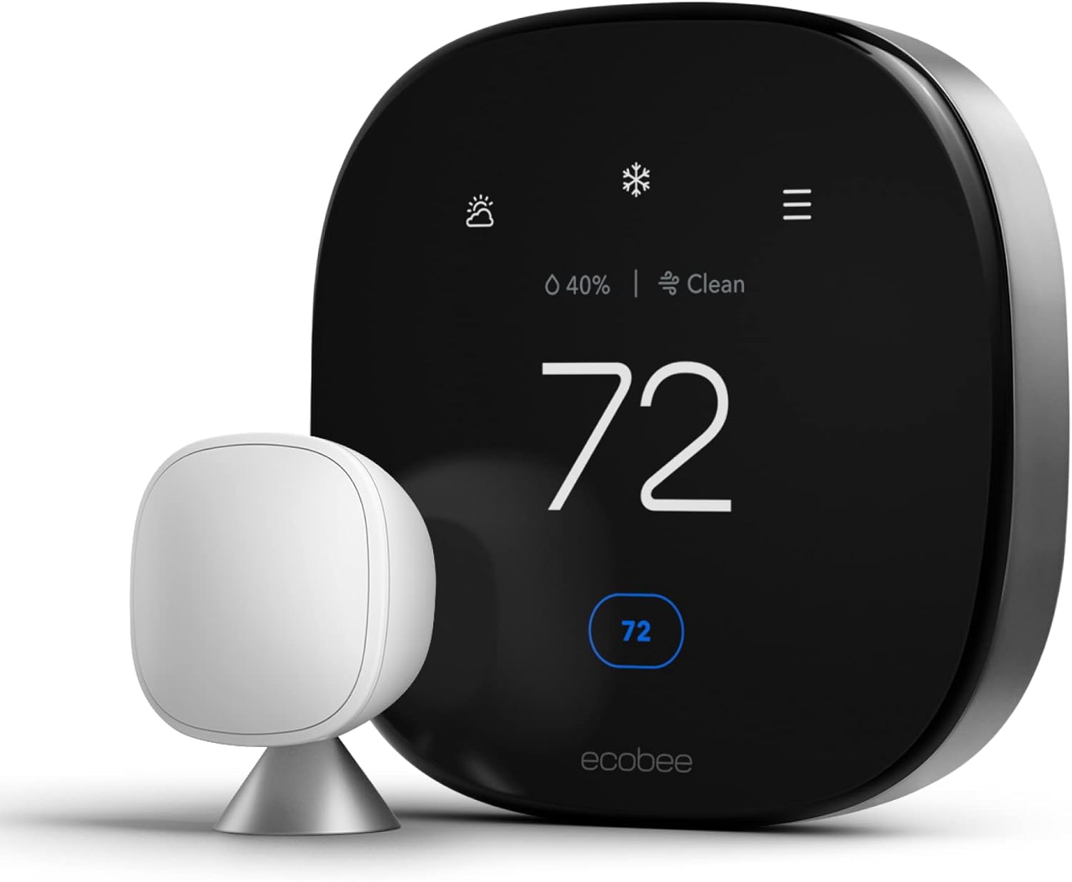
Handles conventional heating/cooling, heat pumps, dual-fuel, and multi-stage systems. Includes SmartSensor, air quality monitoring, and full heat pump O/B configuration support.
ecobee SmartThermostat Premium — Best for Combined Heating & Cooling
Control Logic: How Heating and Cooling Thermostats “Think” Differently
Beyond the wiring differences, heating and cooling control modes involve fundamentally different internal logic — different ways the thermostat decides when to turn equipment on, how long to run it, and when to stop. These differences have real consequences for comfort, efficiency, and equipment longevity.
Setpoint Direction and the Deadband
In heating mode, the thermostat calls for heat when the measured temperature falls below the heating setpoint minus the deadband. If your setpoint is 70°F and the deadband is 1°F, the heating call activates when the room drops to 69°F and deactivates when it rises back to 70°F.
In cooling mode, the logic inverts: the thermostat calls for cooling when the temperature rises above the cooling setpoint plus the deadband. With a 74°F cooling setpoint and 1°F deadband, cooling activates at 75°F and deactivates at 74°F.
On combined heat/cool thermostats, the heating and cooling setpoints must maintain a minimum separation — called the setpoint separation or deadband between modes. Most thermostats enforce a minimum 3–5°F gap between the heating setpoint and cooling setpoint to prevent the two modes from fighting each other. If you set heat to 72°F and cooling to 73°F, a properly programmed thermostat will automatically push one setpoint outward to maintain the required gap.
Anticipator Logic: Heating’s Unique History
Older mechanical (bimetal) thermostats included a component called a heat anticipator — a small resistor that slightly warmed the bimetal coil, causing the thermostat to call off heat a few minutes before the setpoint was actually reached. This compensated for the thermal lag of the heating system: by the time the furnace fully shuts down and the blower coasts to a stop, the room’s temperature continues rising from residual heat in the ducts and heat exchanger. Without anticipation, the room would consistently overshoot the setpoint.
Modern digital and smart thermostats replace this crude mechanical compensator with adaptive algorithms that learn how long your specific system takes to reach setpoint and begin ramping down the call signal accordingly. This is part of why smart thermostats like the Nest and ecobee improve efficiency over dumb digital replacements — their overshoot correction is dynamic rather than static.
Cooling systems don’t need an equivalent anticipator in the same way, because refrigerant-based cooling stops almost immediately when the compressor shuts off, with minimal thermal lag compared to a hot heat exchanger.
Minimum On/Off Time Enforcement
The control logic for cooling includes protections that heating logic doesn’t require in the same form:
- Minimum compressor on-time: Prevents the AC from running for less than a minimum period (typically 3–5 minutes), protecting against rapid short-cycling that causes compressor overheating
- Off-cycle delay: After the compressor shuts off, the thermostat waits a set period (3–5 minutes by default on most smart thermostats, adjustable up to 5 minutes) before allowing a new cooling call. This allows refrigerant head pressure to equalize before the compressor restarts
- Defrost coordination (heat pump only): Heat pump thermostats must coordinate with the outdoor unit’s defrost cycle — temporarily suppressing auxiliary heat during defrost to prevent simultaneous operation that can trip circuit breakers
- Trigger: Room temp drops below heating setpoint
- Lag compensation: Heat anticipator (mechanical) or adaptive algorithm (digital/smart)
- Overshoot risk: High due to duct/heat exchanger thermal mass
- Min runtime enforcement: Less critical; furnaces tolerate shorter cycles
- Post-call behavior: Blower continues for cool-down period (set by furnace board)
- Trigger: Room temp rises above cooling setpoint
- Lag compensation: Minimal; evaporator coil cools rapidly
- Overshoot risk: Lower; refrigerant stops quickly
- Min runtime enforcement: Critical — short cycles damage compressor
- Post-call behavior: 3–5 min lockout before new compressor start
Single-Stage vs. Multi-Stage: How Staging Differs Between Heat and Cool
The concept of staging — running equipment at partial capacity before full capacity — applies to both heating and cooling, but it operates differently in each mode and requires specific thermostat support to function correctly.
Why Staging Matters
A single-stage furnace operates at 100% capacity every time it fires. A two-stage furnace operates at roughly 65–70% capacity on first stage and 100% on second stage, bringing on second stage only when first stage can’t satisfy demand within a set time window. The efficiency and comfort advantages of two-stage operation are significant: longer, gentler heating cycles distribute heat more evenly, reduce temperature swings, and operate at lower energy consumption most of the time.
The same principle applies to two-stage compressors in central AC systems — first stage runs at lower capacity for mild cooling loads, second stage activates for peak demand days.
Two-Stage Heating vs. Two-Stage Cooling: What the Thermostat Does Differently
For two-stage heating, the thermostat sends a first-stage call on W1 and waits a configured period (typically 5–10 minutes). If the room temperature hasn’t started rising toward the setpoint within that window, the thermostat escalates to W2, bringing on the second stage. The escalation timer is configurable on smart thermostats — a longer timer maximizes first-stage efficiency, while a shorter timer prioritizes faster recovery.
Two-stage cooling follows the same logic on Y1 and Y2. However, there’s an additional consideration: two-stage cooling significantly improves humidity removal. At first-stage capacity (lower airflow, longer runtime), the evaporator coil has more time to condense moisture from the air before it’s blown back into the space. This is why two-stage AC systems are particularly valued in humid climates — and why the thermostat’s staging timer configuration affects not just temperature but indoor air quality.
For an in-depth comparison of how the two leading smart thermostats handle multi-stage systems, our Nest vs. Honeywell multi-stage HVAC comparison covers the configuration options and real-world performance differences in detail.
Heat Pumps: When Heating and Cooling Merge Into One System
Heat pumps represent the most significant complication in the heating-vs-cooling thermostat conversation — because a heat pump is the same physical equipment providing both functions. A heat pump is essentially an air conditioner that can run in reverse: in summer, it moves heat from inside your home to outside (cooling); in winter, it extracts heat from outdoor air and moves it inside (heating). The refrigerant cycle is the same; only the direction of flow changes.
This reversal is controlled by a component called the reversing valve (or four-way valve). And controlling the reversing valve is the job of the thermostat’s O or B terminal — a terminal that exists nowhere on a conventional heating-only or cooling-only thermostat.
The O/B Terminal: Heat Pump’s Defining Wire
The O/B wire is exclusive to heat pump systems. It sends a 24V signal to energize or de-energize the reversing valve solenoid, determining whether the refrigerant flows in cooling direction or heating direction. The convention varies by manufacturer:
| Brand / System | O Terminal (energized in…) | B Terminal (energized in…) |
|---|---|---|
| Trane, Carrier, Lennox, Goodman, American Standard | Cooling mode ✓ | Not used |
| Rheem, Ruud (some older models) | Not used | Heating mode ✓ |
| Most modern systems (2010+) | Cooling mode ✓ (O) | Rare |
This is why heat pump thermostat setup includes an O/B configuration step — you must specify whether the reversing valve energizes in cooling mode (O) or heating mode (B). Getting this wrong results in the heat pump heating when you ask for cooling and cooling when you ask for heating. It’s one of the most common installation mistakes with heat pump thermostat replacements.
Auxiliary and Emergency Heat: Heating-Exclusive Heat Pump Features
Heat pumps lose efficiency as outdoor temperatures drop. Below a certain outdoor temperature — the balance point, typically between 25°F and 40°F depending on the system — the heat pump can’t extract enough heat from outdoor air to maintain indoor comfort efficiently. At this point, the system relies on backup electric resistance heating elements (auxiliary heat) to supplement the heat pump’s output.
Heat pump thermostats handle this in two ways:
- Auxiliary Heat (AUX): Automatically activated by the thermostat when the heat pump has been running but can’t satisfy the setpoint within a configured time window, or when outdoor temperature drops below a set threshold. The heat pump continues running alongside the auxiliary elements.
- Emergency Heat (EM HT): A manually selected mode that completely bypasses the heat pump and runs the resistance elements alone. Used only if the heat pump has failed. Emergency heat is expensive to run — electric resistance heat costs 2–3× more than heat pump mode at the same outdoor temperature — and should never be used as a routine heating mode.
These functions have no equivalent in conventional heating-only or cooling-only thermostat configurations. They’re features that only exist because the heat pump combines both functions in hardware that requires specialized thermostat coordination. If you’re unsure whether a bad thermostat is causing your heat pump’s heating to fail, the AUX/EM configuration is often the first place to check.

Google Nest Learning Thermostat (4th Gen) — Top Pick for Heat Pump Homes
Configurable O/B reversing valve support, auxiliary heat management, Soli radar presence sensing, and Matter compatibility. Handles single-stage heat pumps with elegance.
🛒 Check Price on AmazonDual-Fuel Systems: When Heating and Cooling Have Different Brains
Dual-fuel (or hybrid) HVAC systems pair a heat pump with a gas furnace — using the heat pump’s efficiency for mild weather and the furnace’s raw heat output for the coldest conditions. This configuration delivers the best of both worlds in terms of operating cost, but it adds a new layer of thermostat complexity: the thermostat must now manage two separate heating sources as well as the heat pump’s cooling function.
The Balance Point Decision
The central challenge in dual-fuel control is the balance point calculation. Below a certain outdoor temperature (the balance point), running the gas furnace costs less per BTU than running the heat pump with heavy auxiliary electric heat. The thermostat’s job is to automatically switch between the two heat sources at this threshold.
Balance points typically fall between 30°F and 40°F in most U.S. climates, but the optimal point depends on local gas prices, electricity rates, and the specific heat pump’s performance curve. Smart thermostats with dual-fuel support — including select ecobee models and Honeywell Home’s T-series — allow you to configure this balance point temperature directly in the thermostat settings.
Wiring Complexity in Dual-Fuel Setups
A dual-fuel system requires both heat pump wiring (Y, O/B, AUX/W2) and furnace wiring (W1) at the thermostat. The thermostat must have dedicated logic to decide: is the outdoor temperature above or below the balance point? If above, call the heat pump via Y and O/B. If below, call the furnace via W1 and suppress the heat pump call. This logic doesn’t exist in standard thermostats — it requires a thermostat explicitly designed or configurable for dual-fuel operation.
Thermostat Types by System: Which Controller Does What
Now that the underlying differences in heating and cooling control are clear, let’s map those differences to the specific thermostat types available and what each is designed to manage.
| Thermostat Type | Heating | Cooling | Heat Pump | Dual-Fuel | Multi-Stage |
|---|---|---|---|---|---|
| Heating-Only | ✅ | ❌ | ❌ | ❌ | Rarely |
| Cooling-Only | ❌ | ✅ | ❌ | ❌ | Rarely |
| Heat/Cool Conventional | ✅ | ✅ | ❌ | ❌ | Some |
| Heat Pump Thermostat | Via HP | Via HP | ✅ | ❌ | Some |
| Smart Thermostat (standard) | ✅ | ✅ | ✅ | Varies | ✅ |
| Smart Thermostat (premium) | ✅ | ✅ | ✅ | ✅ | ✅ |
| Line-Voltage (baseboard) | ✅ (240V) | ❌ | ❌ | ❌ | ❌ |
| Radiant/Hydronic | ✅ (specialized) | ❌ | ❌ | ❌ | Some |
Heating-Only Thermostats: Still Relevant in 2026
Heating-only thermostats aren’t obsolete — they’re the correct solution for homes with hydronic (hot water) radiant systems, electric baseboard heat (which uses line-voltage models), steam heating systems, and boilers. These systems have no cooling function, so a combined heat/cool thermostat’s Y terminal and compressor protection logic are simply irrelevant and wasted complexity. Dedicated heating controllers often offer features specifically useful for these systems, like outdoor temperature reset for hydronic systems or adaptive start for boilers.
Cooling-Only Thermostats: Rare but Relevant in Hot Climates
Cooling-only thermostats exist primarily in regions where heating is never needed — parts of Florida, Southern California, Hawaii, and similar climates where homes have window units or mini-splits for cooling but no central heating system. They’re rarely purchased as primary thermostats for typical U.S. homes, but understanding that they exist clarifies why the W terminal is absent on some devices.
Smart Thermostats: How They Handle Heating vs. Cooling Differently
Modern smart thermostats don’t just replace the basic switching function of older thermostats — they add layers of intelligence specifically tuned to each mode’s characteristics. Understanding how smart thermostats handle heating and cooling differently reveals why setup configuration matters so much.
Mode-Specific Learning and Scheduling
Smart thermostats with adaptive learning — the Nest Learning Thermostat being the canonical example — observe how quickly your home heats versus how quickly it cools, storing separate thermal models for each mode. A home that heats from 65°F to 70°F in 18 minutes might cool from 76°F to 72°F in 25 minutes. The thermostat uses these mode-specific models to determine when to start a heating or cooling cycle so the home reaches the setpoint exactly at the programmed time, rather than starting the cycle at the programmed time and reaching setpoint later.
This Early Start (or Pre-Conditioning) feature applies differently to heating and cooling because the thermal lag characteristics are different. In heating mode, overshoot is the main risk — the furnace’s residual heat keeps warming the space even after the thermostat shuts off the call. In cooling mode, the risk is understoot — the house warms faster than expected on high-load days and the AC can’t recover in time. Smart thermostats model these asymmetric behaviors separately.
Geofencing Behavior in Heat vs. Cool Mode
Geofencing — using your phone’s location to automatically adjust the thermostat when you leave or approach home — behaves differently depending on which mode is active. In cooling mode, the thermostat typically allows the home to drift warmer when you’re away (energy savings) and pre-cools before you arrive. In heating mode, it allows the home to drift cooler when empty and pre-heats before arrival. The magnitude of the temperature drift and the advance start time are configurable independently for heating and cooling in most smart thermostats.
The efficiency gains from geofencing are particularly strong in cooling mode in warm climates, where manually forgetting to raise the setpoint when leaving is common and costly. Our analysis of how geofencing cuts HVAC runtime and costs breaks down the savings data by climate zone and system type.
Humidity Control: A Cooling-Dominant Concern
Dehumidification is a byproduct of air conditioning — as air passes over the cold evaporator coil, moisture condenses and drains away. Smart thermostats increasingly incorporate humidity sensors and cooling-mode logic to optimize dehumidification. ecobee’s “Feel Like” mode and Honeywell’s humidity sensing use real-time relative humidity to adjust the cooling setpoint downward when humidity makes the room feel warmer than the thermometer reads. This logic applies only in cooling mode — there’s no dehumidification function in heating.
Heat Pump Mode vs. Cooling Mode: The Smart Thermostat’s Coordination Challenge
When a smart thermostat controls a heat pump, it must continuously evaluate outdoor conditions and determine whether heat pump heating mode is appropriate or whether auxiliary heat should be staged in. This requires integrating outdoor temperature data — either from a built-in outdoor sensor, from a connected weather service (used by ecobee and Nest), or from a dedicated outdoor sensor. The thermostat’s decision-making around AUX heat activation thresholds has a significant impact on operating cost.
For a head-to-head look at how the two leading smart thermostats handle this specific challenge, our comparison of Nest vs. Honeywell for multi-stage heat pump systems provides detailed configuration guidance.

Honeywell Home T9 — Best Multi-Room Heat & Cool Management
Remote SmartRoom sensors for accurate heating and cooling in every zone, geofencing, flexible scheduling, and excellent two-stage HVAC support.
🛒 Check Price on AmazonHow to Choose the Right Thermostat for Your System
Given everything above, the practical question becomes: what thermostat do you actually need? The answer depends on four factors: your heating system type, your cooling system type (or absence of one), the number of stages each supports, and whether you want smart features.
| Your HVAC System | Thermostat Needed | Key Terminals Required | Smart Option |
|---|---|---|---|
| Gas furnace only (no AC) | Heating-only or heat/cool | R, W, G, C | Any smart thermostat |
| Gas furnace + central AC | Combined heat/cool | R, W, Y, G, C | Nest, ecobee, Honeywell T6-T9 |
| 2-stage furnace + 2-stage AC | 2-stage heat/cool | R, W1, W2, Y1, Y2, G, C | ecobee, Honeywell T9/T10, Sensi Touch |
| Single-stage heat pump | Heat pump thermostat | R, Y, G, O/B, AUX/W2, C | Nest, ecobee, most smart models |
| 2-stage heat pump | 2-stage heat pump | R, Y1, Y2, O/B, AUX, C | ecobee Premium, Honeywell T10 Pro |
| Dual-fuel (HP + gas) | Dual-fuel smart thermostat | R, Y, W, O/B, AUX, C | ecobee Premium, Honeywell T10 Pro |
| Electric baseboard (240V) | Line-voltage thermostat | L1, L2 (240V) | Mysa Smart Thermostat |
| Hydronic/radiant heat only | Heating-only or specialized | R, W, C (or dry contact) | Ecobee, Nest (with compatible boiler) |
The Compatibility Check Process
Before purchasing any thermostat, use the manufacturer’s compatibility checker with your specific HVAC equipment model numbers. Both Google (Nest) and ecobee offer online compatibility tools. If you’re uncertain about your current wiring, photograph the existing thermostat’s terminal connections before removal — the wire colors and terminal letters tell you exactly what system type you have.
Also check whether your home has a C-wire. Without a common wire providing continuous 24V power, many smart thermostats won’t operate reliably. If your current thermostat has only 4 wires (R, W, Y, G), check your thermostat cable bundle at the air handler — there’s often an unused conductor that can serve as a C-wire without running new cable.
For a complete walk-through of HVAC compatibility by system type, our thermostat-to-furnace compatibility guide covers every major system configuration with wiring diagrams and compatibility matrices.
Common Mistakes When Mixing Heating and Cooling Thermostat Configurations
Understanding the differences between heating and cooling thermostat control prevents a set of surprisingly common — and costly — installation errors. Here are the mistakes that HVAC technicians encounter most frequently.
Mistake 1: Installing a Conventional Thermostat on a Heat Pump
This is the single most common heat pump thermostat error. A conventional heat/cool thermostat has no O/B terminal and no auxiliary heat management. When installed on a heat pump, it will send a W (heat) signal to the system — but on a heat pump, the W terminal activates auxiliary resistance heat directly, bypassing the heat pump’s efficient refrigerant cycle entirely. The home heats using expensive resistance elements 100% of the time instead of the efficient heat pump. Many homeowners don’t notice for months, only discovering the problem when their electricity bill doubles.
Mistake 2: Wrong O/B Configuration
As covered earlier, some systems energize the reversing valve in cooling mode (O); others in heating mode (B). Setting this incorrectly in the thermostat setup reverses the heat pump’s operating modes — heat when you want cool, cool when you want heat. Always confirm which convention your outdoor unit uses before completing heat pump thermostat setup.
Mistake 3: Bridging Rh and Rc When Two Transformers Are Present
On systems with separate heating and cooling transformers, bridging Rh and Rc creates a short circuit between two 24V sources. The result is a blown transformer fuse, a dead thermostat, or a tripped breaker at the air handler. If you find two red wires at the old thermostat — one on Rh, one on Rc — they must connect to their respective terminals on the new thermostat without bridging.
Mistake 4: Ignoring the Setpoint Separation Requirement
Setting the heating setpoint very close to the cooling setpoint (e.g., heat at 70°F, cool at 71°F) in mild weather causes the system to switch back and forth between modes rapidly — essentially fighting itself. Most thermostats enforce a minimum 3–5°F separation between the heat setpoint and the cool setpoint precisely to prevent this, but some manual-configuration setups allow it. Maintain at least a 4°F gap between your heating and cooling setpoints for stable operation.
Mistake 5: Using Emergency Heat as a Normal Heating Mode
Emergency heat on a heat pump thermostat bypasses the efficient refrigerant cycle and runs resistance elements alone. Some homeowners engage EM HT during cold snaps thinking it will heat the home faster — which it does, but at 2–3× the operating cost. Emergency heat is for use only when the heat pump itself is malfunctioning. If your heat pump isn’t keeping up in cold weather, the correct response is to check AUX heat staging settings, not switch to EM HT.
Seasonal Operation Tips: Getting the Most from Heating and Cooling Modes
Understanding the mechanical differences between heating and cooling control modes leads naturally to better seasonal operating strategies. Here’s how to get the most efficiency and comfort from each mode throughout the year.
Heating Season Best Practices
- Use setback scheduling aggressively: Lowering the setpoint by 7–10°F during sleeping hours (typically 10pm–6am) and when the home is empty delivers 5–15% heating energy savings without sacrificing comfort. The key is using the thermostat’s recovery algorithm to pre-heat before occupied periods.
- Fan mode: set to AUTO, not ON: In heating mode, running the fan continuously (ON mode) circulates unheated air from cold ductwork during the off-cycle, actually cooling the home slightly between furnace cycles. Auto mode activates the fan only when the furnace is running warm air.
- Don’t crank the setpoint to heat faster: Raising the setpoint to 80°F when you want 70°F doesn’t heat your home faster — furnaces deliver heat at a constant rate regardless of setpoint. It just means the system will overshoot and waste energy overheating the space.
- Monitor auxiliary heat usage on heat pumps: Smart thermostats with app reporting show how often AUX heat activates. Frequent AUX activation on mild-weather days (above 35°F) suggests the heat pump may need servicing or the AUX threshold is set too aggressively.
Cooling Season Best Practices
- Don’t lower the setpoint dramatically to cool faster: Same principle as heating — AC equipment delivers cool air at a fixed rate regardless of how far below the setpoint you set the target. Extremely low setpoints waste energy and risk over-cooling.
- Use pre-cooling before peak electricity rates: In time-of-use utility pricing areas, pre-cooling the home to 70°F before 4pm peak rates kick in, then allowing the setpoint to drift to 76°F during peak hours, can significantly reduce electricity costs without noticeable comfort impact.
- Set fan to AUTO to preserve dehumidification: Continuous fan operation (ON mode) in cooling mode reduces dehumidification — moisture that condenses on the evaporator coil gets re-evaporated into the air stream during the off-cycle. AUTO mode preserves the dehumidification benefit.
- Enable geofencing for significant savings: Cooling an empty house is one of the biggest energy wastes in residential HVAC. Geofencing that raises the setpoint when you leave and pre-cools before you return can reduce AC runtime by 20–30% in warm climates.
For a data-backed look at optimal setpoint strategies across seasons, our guide to winter thermostat scheduling for comfort and efficiency and the science behind optimal sleep temperatures provide specific setpoint recommendations backed by research.

Emerson Sensi Touch 2 — Best Value for Heat/Cool Conventional Systems
Illuminated terminals for easy installation, full 2-stage heat/cool support, geofencing, and a color touchscreen — at a price that makes it the easiest smart upgrade for a standard furnace + AC home.
🛒 Check Price on AmazonFrequently Asked Questions
No. A heating-only thermostat has terminals for R (power), W (heat call), and sometimes G (fan), but it lacks the Y terminal needed to send a cooling call to the compressor contactor. Without the Y terminal, the thermostat physically cannot trigger the AC compressor. You need at minimum a combined heating/cooling thermostat that includes both W and Y terminals for a conventional forced-air system.
Rh (red-heat) and Rc (red-cool) are separate 24V power feeds from two different transformers — one dedicated to the heating system and one to the cooling system. Most homes with a single integrated HVAC system have a single transformer with a jumper bridging Rh and Rc. Dual-transformer systems (common with heat pump plus gas backup, or separate heating and cooling equipment) have distinct transformers that must not be bridged — each red wire connects to its respective Rh or Rc terminal independently.
The O/B wire controls the reversing valve on a heat pump, which determines the direction of refrigerant flow — and therefore whether the heat pump operates in heating mode or cooling mode. Most major brands (Trane, Carrier, Lennox, Goodman) energize the reversing valve in cooling mode via the O terminal. Some older systems (Rheem, Ruud) use the B terminal convention and energize in heating mode. This configuration must be set correctly in the thermostat setup — getting it wrong causes the heat pump to heat when cooling is called and vice versa.
Yes — virtually all modern smart thermostats are designed as combined heating and cooling controllers with a single hardware platform. They manage heat calls (W), cooling calls (Y), fan calls (G), and auxiliary/emergency heat in heat pump systems. During setup, you configure the thermostat for your specific system type — conventional, heat pump, or dual-fuel — and it applies the correct control logic for each mode automatically. Most also support two-stage heating and cooling at no additional cost.
A single-stage thermostat sends a simple on/off signal — W1 for heat, Y1 for cool — with no ability to request partial capacity from the HVAC equipment. A two-stage thermostat can send a first-stage call (W1/Y1) for moderate demand and a second-stage call (W2/Y2) for peak demand when the first stage can’t satisfy the setpoint within a configured time window. Two-stage control provides better efficiency and more even temperature distribution by running at lower capacity most of the time, escalating to full capacity only when needed.
Yes — this is a dual-fuel or hybrid system configuration. Specialized smart thermostats monitor outdoor temperatures and automatically switch between the heat pump (efficient at mild temperatures) and the gas furnace (more cost-effective below the balance point, typically 30–40°F depending on local energy prices). Not all smart thermostats support dual-fuel mode — ecobee Premium and Honeywell Home T10 Pro are among the most capable options. Standard configurations of the Nest Learning Thermostat have limited dual-fuel support.
Emergency heat (EM HT) is a manually activated mode that bypasses the heat pump’s refrigerant cycle entirely and powers the backup resistance heating elements directly. It should only be used if the heat pump itself is malfunctioning — a frozen outdoor coil, a failed compressor, or a refrigerant leak that prevents normal operation. Running on emergency heat routinely costs 2–3× more per hour than heat pump mode at the same outdoor temperature and provides no efficiency advantage. If your heat pump isn’t keeping up in cold weather, check AUX heat activation settings rather than switching to emergency heat.
W1 and W2 correspond to first-stage and second-stage heating calls. W1 activates the first burner stage on a two-stage gas furnace — typically 65–70% of full capacity — for typical heating demand. W2 brings on the second burner stage at full capacity when the first stage can’t satisfy the demand within a set time window, or during extreme cold weather. On heat pump systems, W2 activates the auxiliary electric resistance heating elements when the heat pump’s output alone isn’t sufficient. Not all systems use W2 — single-stage equipment only uses W1.
At the budget end, heat pump thermostats are priced similarly to conventional heat/cool models ($30–$60 for basic programmable units). Smart thermostats with full heat pump support — including dual-fuel, multi-stage, and configurable O/B settings — generally run $150–$260, comparable to premium smart thermostats for conventional systems. The ecobee SmartThermostat Premium and Honeywell Home T10 Pro offer the most comprehensive heat pump feature sets, including dual-fuel support, in the smart thermostat category.
This is the compressor protection delay (also called short-cycle protection or off-cycle lockout) working correctly. After the compressor shuts off, refrigerant pressures are unequal between the high-pressure side and low-pressure side. Attempting to restart immediately requires the compressor motor to work against this pressure differential, risking motor overload and mechanical damage. The thermostat enforces a 3–5 minute waiting period for pressures to equalize before allowing a new cooling call. This is a feature, not a malfunction — and it’s one of the reasons not to override the thermostat’s cooling delay settings.
Conclusion: Two Modes, One Device, Many Variables
Heating and cooling thermostats may look identical on the wall — and in most modern homes, they’re literally the same device. But beneath that shared hardware lies fundamentally different control logic, different wiring terminals, different staging behavior, and entirely different considerations for heat pump systems that blur the heating/cooling boundary entirely.
Understanding these differences isn’t just academic. It’s the knowledge that prevents you from installing a conventional thermostat on a heat pump and paying three times your expected heating bill. It’s what helps you correctly configure two-stage staging to maximize equipment efficiency. It’s what tells you why the O/B wire configuration matters so much, and why bridging Rh and Rc when you have two transformers will blow a fuse instantly.
For most homeowners with a standard gas furnace and central AC, a quality combined heat/cool smart thermostat handles both modes seamlessly with minimal configuration. For those with heat pumps, dual-fuel systems, multi-stage equipment, or specialized heating systems, the additional complexity is real — but manageable with the right thermostat choice and a clear understanding of what each wire actually does.
Whether you’re buying your first smart thermostat, troubleshooting a system that behaves strangely in one mode but not the other, or simply trying to understand what’s happening inside that small box on your wall — the principles covered here give you the foundation to make better decisions, ask better questions, and get more from your HVAC system year-round.
Ready to Find the Right Thermostat for Your System?
Use our compatibility guide and expert reviews to match the perfect thermostat to your heating, cooling, or heat pump setup — and start saving from day one.
🔍 Check Your Compatibility Now →